Google Tag

Showing posts with label Arduino. Show all posts

Friday, July 15, 2016

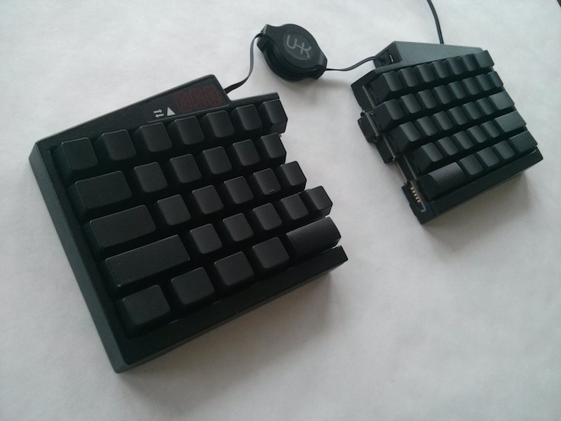
Arduino based Developer's Dream Keyboard


BY LÁSZLÓ MONDA - SOFTWARE ENGINEER @ TOPTAL


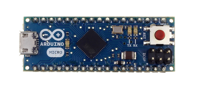
 The Arduino Micro development board is an ideal candidate for this purpose, because it features the ATmega32U4 microcontroller - an AVR microcrontroller and the same processor that is the brains of the UHK.


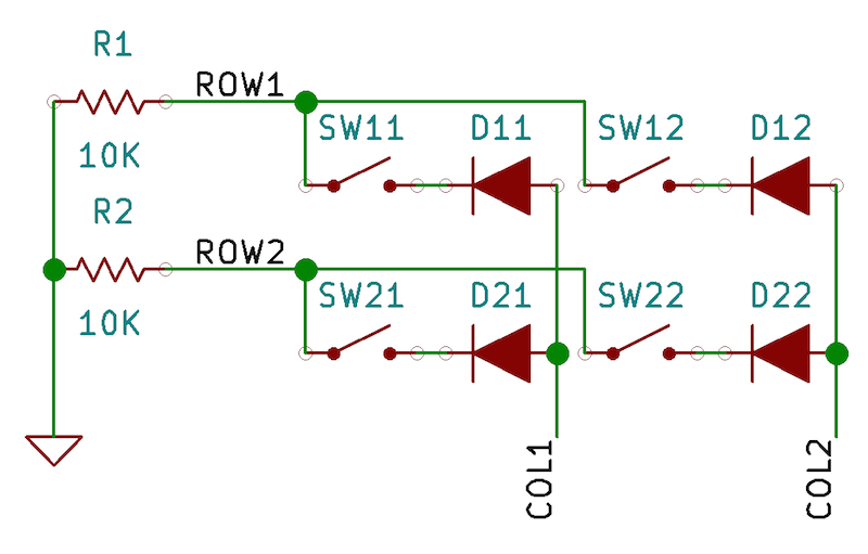
A full-sized 104-key keyboard could have 18 rows and 6 columns but we’ll simply have a humble 2x2 keyboard matrix for starting up. This is the schematic:


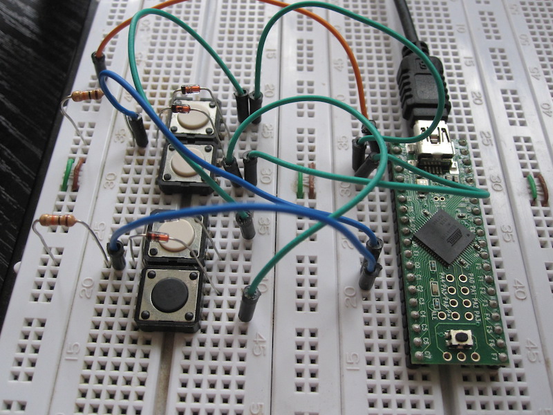
And this is how it looks on a breadboard:


For detailed information about this project follow the link.

Tuesday, May 31, 2016

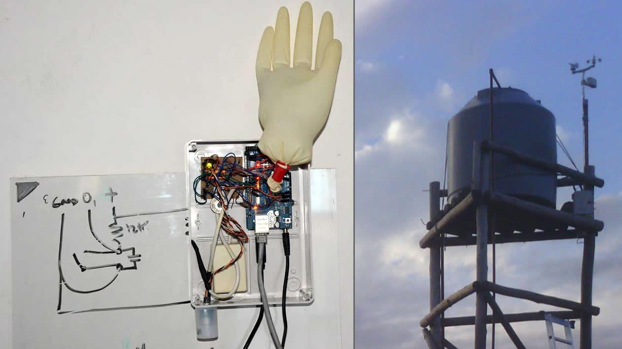
How I Made a Fully-Functional Arduino Weather Station


BY FRANCISCO SANCHEZ CLARIÁ - SOFTWARE DEVELOPER @ TOPTAL


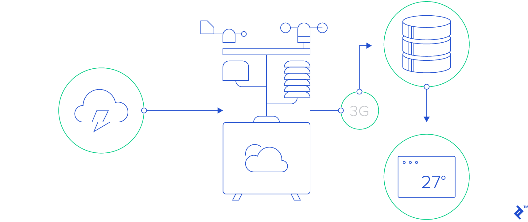
The goal of this project was to deliver real-time weather data to the browser at home.
The key questions and caveats involved in a project like this:

  • How can I create a weather station that it is neither valuable nor attractive to a thief?
  • How can I keep hardware costs and development time to the minimum?
  • How can I measure and access weather data in real time and display it in a useful way?
  • Required measurements: wind and wind gusts, wind direction, rain, atmospheric pressure, temperature, humidity
  • Connect station to Internet
  • Store and retrieve local weather data
  • Communicate between weather station and server
  • How can I reduce maintenance to (almost) zero?
  • Manage hanging of software
  • Manage loss of connectivity
  • Manage loss of energy supply


For detailed information about this project follow the link.
How I Made a Fully-Functional Arduino Weather Station


Friday, May 06, 2016

Arduino Your Home & Environment: Monitoring voltage of a dc battery supply

Arduino Your Home & Environment: Monitoring voltage of a dc battery supply by Steve Spence:


Since we are involved in off grid solar power systems, we have a need to monitor battery voltage. The Arduino can do this easily with a simple voltage divider. With some simple mods, we can control loads, generators, or notifications based on battery voltage.


To read a maximum of 20vdc, R1 should be 3k ohm, R2 should be 1k ohm, and the code would be as follows:


/*

DisplayMoreThan5V sketch

prints the voltage on analog pin to the serial port

Do not connect more than 5 volts directly to an Arduino pin.

*/


const int referenceVolts = 5; // the default reference on a 5-volt board

//const float referenceVolts = 3.3; // use this for a 3.3-volt board


const int R1 = 3000; // value for a maximum voltage of 20 volts

const int R2 = 1000;

// determine by voltage divider resistors, see text

const int resistorFactor = 255 / (R2/(R1 + R2));

const int batteryPin = 0; // +V from battery is connected to analog pin 0


void setup()

{

Serial.begin(9600);

}


void loop()

{

int val = analogRead(batteryPin); // read the value from the sensor

float volts = (val / resistorFactor) * referenceVolts ; // calculate the ratio

Serial.println(volts); // print the value in volts

}
Arduino Basics: Bluetooth Tutorial 1

Arduino Basics: Bluetooth Tutorial 1 by Scott C:  

Introduction: The bluetooth shield used in this project is a great way to detach the Arduino from your computer. What is even better, is that the shield allows you to control your arduino from your mobile phone or other bluetooth enabled device through simple Serial commands. In this tutorial we will connect a Grove Chainable RGB LED to the bluetooth shield directly, and send simple commands using the Bluetooth SPP app on a Samsung Galaxy S2 to change the colour of the LED (Red , Green and Blue)

Notes:
You don't need to download a library to get this project running. But if you plan to use bluetooth shields to get 2 Arduinos to communicate to each other, then I would advise that you download the library files (which are just examples) from the Seeedstudio site : here.

Visit this site to setup your phone or laptop for bluetooth communication to the shield - here

The app used on my Samsung Galaxy S2 phone was "Bluetooth SPP"

You will initially need to enter a pin of '0000' to establish a connection to the Bluetooth shield - which will appear as "SeeedBTSlave" or whatever text you place on line 90 of the Arduino code above.


Warning !

Not all phones are compatible with the bluetooth shield. 
If you have used this shield before - please let me know what phone you used - so that we can build a list and inform others whether their phone is likely to work with this project or not. Obviously - those phones that do not have bluetooth within - will not work :).
And I have not tried any other apps either

I got it to work very easily with my Samsung Galaxy S2 using the free Bluetooth SPP app from the google play store.

Arduino Your Home & Environment: Using a 4x4 Keypad

Arduino Your Home & Environment: Using a 4x4 Keypad  by Steve Spence: I was working on a project for someone who needed a keypad for password entry. I couldn't find my 3x4 keypad, but found a 4x4 keypad in one of my parts boxes. I modified the example sketch that comes with the excellent keypad library to work with this particular keypad. I couldn't find a set of extended headers to directly connect the keypad to the Arduino, so I used a small protoboard.


You do need the library from http://playground.arduino.cc/Code/Keypad

I connected all the pins from the keypad, from left to right, to 9-2 on the Arduino. Key output shows in the Serial Monitor. In Part 2 I'll show how to accept and compare passwords.

Sunday, December 29, 2013

Arduino Controlled dual axis Solar Tracker


Arduino Controlled dual axis Solar Tracker by Kostas Kokoras

It's a Solar Tracker project with the Arduino Duemilanove upgraded with atmega328 which controls two linear actuators with 24V DC motors. It calculates the position of sun in the sky in degrees (elevation & azimuth) according to date and time which gets from a i2c RTC (DS1307) and the coordinates of the place is installed also.      

Είναι μια κατασκευή Solar Tracker με το Arduino Duemilanove αναβαθμισμένο με  τον atmega328 η οποία οδηγεί δύο μοτέρ 24V dc (linear actuators).Υπολογίζει την θέση του ήλιου στον ουρανό σε μοίρες (elevation & azimuth) βάση την ημερομηνία και την ώρα, τα οποία τα παίρνει από ένα i2c RTC (DS1307), αλλά και τις συντεταγμένες του σημείου εγκατάστασης.

The theory of sun position calculations is here
Η θεωρία για τον υπολογισμό της θέσης του ήλιου βρίσκεται εδώ
http://www.pveducation.org/pvcdrom/properties-of-sunlight/motion-of-sun

Watch the video...
Δείτε το βίντεο...


Arduino Controlled dual axis Solar Tracker


Potentiometer
For the measurements of the degrees i put a potentiometer on each axis. Arduino ADC converts the potentiometer reading to degrees, 30-90 degrees for Elevation and 120-240 degrees for Azimuth. Potentiometers aren't so accurate with angle measurement, i suppose decoders will do better job but they cost more.

Ποτενσιόμετρο
Για την μέτρηση των μοιρών του tracker στον κάθε άξονα προσάρμοσα από ένα ποτενσιόμετρο και ένα μοιρογνωμόνιο. Το arduino μετατρέπει (ADC) την τιμή του ποτενσιόμετρου σε μοίρες, για το Elevation 30-90 μοίρες και το Azimuth 120-240 μοίρες. Τα ποτενσιόμετρα δεν μου δίνουν μεγάλη ακρίβεια στις μοίρες. Θα ήταν καλύτερα πιστεύω Encoders αλλά με ανάλυση 360 μοιρών για μέγιστη ακρίβεια. Φυσικά αυτό ανεβάζει το κόστος.


On/Off Switch
An On/Off switch changes the status of the tracker to "sun tracking mode" so it moves automatically according to the degrees that calculates and to "manual mode" so with four buttons you can activate any (one each time) move by hand. If you press UP and EAST at the same time enters to "calibration mode" so it makes all the moves one by one until each limit switch is reached, so it reads the potentiometer value and stores it to RTC memory

Διακόπτης on/off
Ένας διακόπτης on/off για να αλλάζει κατάσταση σε "sun tracking" όπου κινείται αυτόματα σύμφωνα με τις μοίρες που υπολόγισε και σε "manual" όπου με τέσσερα buttons μπορείς να ενεργοποιήσεις οποιαδήποτε (μια κάθε φορά) κίνηση χειροκίνητα. Αν πατήσεις το UP και το EAST ταυτόχρονα μπαίνει σε "Calibration Mode" όπου κινείται σε όλες τις κατευθύνσεις μία-μία ως ότου ενεργοποιηθεί ο κάθε τερματικός διακόπτης και διαβάζει την τιμή του ποτενσιόμετρου και την αποθηκεύει στην μνήμη του RTC.


RTC DS1307
The DS1307 i2c RTC keeps time, date and weekday and has some memory also. Maybe i should add some capacitors to crystal because it keeps loosing time.

Το i2c RTC DS1307 κρατάει την ώρα, ημερομηνία και ημέρα εβδομάδας αλλά έχει και μνήμη. Εδώ μάλλον πρέπει να βάλω και πυκνωτές στον κρύσταλλο γιατί συνεχώς χάνει την ώρα.


Limit Switches
Four Limit Switches for each limit position of two axlis of tracker and a led to indicate that at least one limit switch is activated.


Τερματικών Διακόπτες
Τέσσερις τερματικοί διακόπτες για τον έλεγχο των ακραίων θέσεων για κάθε κίνηση και ένα led που ανάβει όταν έστω και ένας τερματικός διακόπτης έχει ενεργοποιηθεί.


H-Bridge DC motor control
The two 24V DC motors are controlled through an  H-Bridge with two relays each from here     http://arduino-info.wikispaces.com/DC-Motors. Give some attention to "fly wheel braking" explained there.

Για τον έλεγχο των δύο μοτέρ 24V DC χρησιμοποίησα δύο κυκλώματα ελέγχου μοτέρ σε συνδεσμολογία H-Bridge με ρελέ  από εδώ  http://arduino-info.wikispaces.com/DC-Motors. Δώστε προσοχή στο φαινόμενο "fly wheel braking" το οποίο κάνει τα μοτέρ να "φρενάρουν" μόλις σταματήσει η τροφοδοσία τους.
                             
Download my Android Apps!
Κατεβάστε τις Android εφαρμογές μου!


To download from Google Play scan QR Codes or click the banners.
Για να κατεβάσεις τις εφαρμογές σάρωσε τους QR Codes ή πάτα στις εικόνες.


Finished
Ολοκληρωμένο


I also built a Visual Basic Application to which arduino sends all data to display on monitor with the current Solar Chart.

Έφτιαξα και μια εφαρμογή σε Visual Basic στην οποία στέλνει με την σειριακή το Arduino όλα τα δεδομένα και εμφανίζονται στην οθόνη και με γραφική παράσταση της πορείας του ήλιου.


The earth moves 360 degrees every 24 hours which means 15 degrees per hour or 60 minutes so it is 1 degree every 4 minutes. I programmed the tracker to move every 16 minutes to calculated position 8 minutes advanced from current time, so 2 degrees advanced from sun. At the next 8 minutes sun will come direct to tracker and pass it by 2 degrees and then the tracker will calculate new position and move to it. If the elevation degrees are equal or lees than zero, which means that the sun is set, tracker moves to horizontal position and stays there all night until the sun rises again.


Η γη κάνει 360 μοίρες σε 24 ώρες που σημαίνει 15 μοίρες την 1 ώρα ή τα 60 λεπτά άρα 1 μοίρα κάθε 4 λεπτά. Το έχω προγραμματίσει να κινείται κάθε 16 λεπτά και να πηγαίνει στις μοίρες που αντιστοιχούν σε 8 λεπτά από την δεδομένη στιγμή, άρα 2 μοίρες μπροστά από τον ήλιο. Στα επόμενα 8 λεπτά ό ήλιος θα έρθει κάθετα στο tracker και στα επόμενα 8 λεπτά θα το περάσει κατά 2 μοίρες, οπότε και θα γίνει ο επόμενος υπολογισμός της θέσης και κίνηση του tracker. Όταν το Elevation βρεθεί ίσο με μηδέν ή μικρότερο, που σημαίνει ότι ο ήλιος έχει δύσει, το tracker αυτόματα έρχεται σε οριζόντια θέση και μένει εκεί όλο το βράδυ μέχρι την ανατολή του ηλίου.

The mechanical construction is done from an old fence that was removed. I bet it can hold one real panel for sure or maybe two. the piece of wood i put on has about the same weight of a real panel. The linear actuators are from hospital beds so they can support more than 100Kgr each. I suppose a mechanic must design a construction that is correct for the job, depending of how many panels are gone placed on.

Όσο για την μηχανολογική κατασκευή, μπορώ να πω ότι δεν είναι και ότι καλύτερο, αφού έγινε με πεταμένα σίδερα από παλιό φράχτη, χωρίς την απαραίτητη μηχανολογική μελέτη. Παρόλα αυτά εξυπηρετεί άψογα τον σκοπό της και κρατάει άνετα το βάρος μιας κόντρα πλακέ που έχει περίπου το ίδιο βάρος με ένα φωτοβολταϊκό panel. Τα μοτέρ πάντως (linear actuators) αντέχουν αρκετό βάρος, μπορεί και πάνω από 100Kgr το καθένα, αφού προέρχονται από κινούμενα κρεβάτια σχεδιασμένα προφανώς να αντέχουν το ανθρώπινο βάρος.


Schematics here.
Σχέδια εδώ.

Code for Arduino here. (some comments are in Greek language, Sorry...)
Ο κώδικας για το Arduino εδώ.


The "Timer.h" library is here.
Την βιβλιοθηκη "Timer.h" θα την βρείτε εδώ.

Code for  VB here.

Ο κώδικας για την VB εδώ.

Thank you for your time, don't hesitate to ask or suggest anything.
Ευχαριστώ για τον χρόνο σας, μη διστάσετε να ρωτήσετε ή να προτείνετε κάτι.


Don't forget to visit my YouTube channel here to check out my other Arduino videos.
Μπορείτε να δείτε τα υπόλοιπα Arduino Projects μου στο κανάλι μου στο YouTube εδώ.    

Kostas Kokoras

NOTICE : Use all information in this page (hardware, schematics, Arduino Code, etc) in your own risk. 


ΠΡΟΣΟΧΗ: Η χρήση των πληροφοριών που παρέχονται σε αυτή την σελίδα (μηχανικά, ηλεκτρονικά σχέδια, πρόγραμμα Arduino, κ.α.) γίνεται αποκλειστικά με δικιά σας ευθύνη.

Arduino Inductive Spark Plug Sensor Engine RPM Meter Shift Lights


Arduino Inductive Spark Plug Sensor Engine RPM Meter Shift Lights by Kostas Kokoras 


Arduino Inductive Spark Plug Sensor Engine RPM Meter Shift Lights


[English]
It's an engine (car or motorbike) RPM-Meter with shift lights. It uses an inductive spark plug sensor to sense the sparks. The sensor needs a few (8-10) turns of one clone cable around the spark plug. The signal from the spark plug then drives a transistor which passes 5V pulses to the Schmit Trigger SN74LS14N and then to Pin 2 of Arduino. The Arduino code counts the pulses and then display the results to the two 7-segment displays. The number that is displayed X 100 gives you the RPM of the engine. When the RPM reaches a adjustable through the dip switch then starts to light on the shift lights.

[Ελληνικά]
Πρόκειτε για ένα στροφόμετρο κινητήρα (αυτοκινήτου, μηχανάκι, κ.α.) . Χρησιμοποιεί έναν επαγωγικό αισθητήρα στροφών, με τον οποίο ανιχνεύει την υψηλή τάση στο καλώδιο του μπουζί. Για να γίνει αυτό απαιτείται να υπάρχει ένα τύλιγμα 8-10 στροφών γύρω από το μπουζοκαλώδιο. Προσοχή το καλώδιο του τυλίγματος πρέπει να είναι μονόκλωνο. Κάθε φορά που έχουμε υψηλή τάση στο μπουζοκαλώδιο δημιουργείτε ένας παλμός που οδηγεί το τρανσίστορ ώστε να περάσει ένας παλμός 5V στο SN74LS14N (Schmitt Trigger) για τετραγωνοποίηση του παλμού, ο οποίος με την σειρά του οδειγήται στο Pin 2 του Arduino. Από εκεί και πέρα αναλαμβάνει το λογισμικό το οποίο μετράει του παλμούς, υπολογίζει τις στροφές ανα λεπτό και τις εμφανίζει στα στα 7-segment Led Displays. Ο αριθμός που εμφανίζεται Χ 100 μας δίχνει τις στροφές ανά λεπτό του κινητήρα. Με τα dip switches ρυθμίζεις στις πόσες στροφές θα ανάβουν τα LED του Shift Light.


The Inductive Spark Sensor


Download my Android Apps!
Κατεβάστε τις Android εφαρμογές μου!


To download from Google Play scan QR Codes or click the banners.
Για να κατεβάσεις τις εφαρμογές σάρωσε τους QR Codes ή πάτα στις εικόνες.


You can view the schematics here.

You can have the Arduino Code here.

Don't forget to visit my youtube channel here to check out my other Arduino videos.

NOTICE : Use all information in this page (hardware schematics, Arduino Code, etc) in your own risk.


Arduino Bluetooth Android Remote Control Car


Arduino Bluetooth Android Remote Control Car by Kostas Kokoras 

Arduino Bluetooth Android Remote Control Car


[English]
Its an old RF R/C toy car that i converted it to Bluetooth ( R/C) remote controlled from a smartphone with an application that i made with MIT App Inventor. For the movements i use the Smartphone's internal orientation sensor and some buttons to turn on/off the lights, to activate the horn, to change "gears" and to connect to Bluetooth module of the car.

I removed all the electronics from the car except the motors and i installed 6 new AA 1,2V rechargeable NiMh 1900mAh batteries. I designed new electronics based on Arduino with a HC-05 Bluetooth module and two h-bridge ic's. The SN754410 for steering motor and the L298N for forward/backward motor. For both ic's i connected parallel the channels, 1 with 4 and 2 with 3.

[Ελληνικά]
Πρόκειτε για ένα παλιό τηλεχειριζόμενο με RF αυτοκινητάκι, το οποίο μετατράπηκε σε τηλεχειριζόμενο με BlueTooth και πλέον μπορεί να ελέγχεται από κινητό smartphone μέσω ενός Application που φτιάχτηκε με την εφαρμογή MIT App Inventor. Για τις κινήσεις χρησιμοποιούνται οι εσωτερικοί αισθητήρες του κινητού, καθώς επίσης η εφαρμογή έχει κάποια κουμπιά για start-stop, σύνδεση με το BlueTooth, φώτα, κόρνα και ταχύτητες.

Έχουν αφαιρεθεί τελείως όλα τα παλιά ηλεκτρονικά μέρη εκτός από τα μοτέρ, και εγκαταστάθηκαν 6 καινούργιες επαναφορτιζόμενες μπαταρίες ΑΑ 1,2V NiMh 1900mAh. Το κύκλωμα οδήγησης βασίζεται στο Arduino με το HC-05 Bluetooth module και δύο οδηγούς για τα μοτερ (h-bridge). Το SN754410 για το μοτερ του τιμονιού (δεξιά-αριστερα) και το L298N για το μοτερ κίνησης (μπρος- πίσω). Και στους δύο παραπάνω οδηγούς έχουν συνδεθεί παράλληλα τα κανάλια 1 με 4 και 2 με 3 για περισσότερη ισχύ. (περισσότερο ρεύμα ανά μοτερ).
Here are some pictures of the building procedure

Arduino Bluetooth Android Remote Control Car by Kostas Kokoras


You can view the schematics here.


Download my Android Apps!
Κατεβάστε τις Android εφαρμογές μου!


To download from Google Play scan QR Codes or click the banners.
Για να κατεβάσεις τις εφαρμογές σάρωσε τους QR Codes ή πάτα στις εικόνες.


You can have the Arduino Code here.
You can have the APK file for the Android here, it is designed for Samsung Galaxy SIII mini, and i dont know how it will look or work to other Android devices.
You can have the source files for AppInventor here so you can modify to your needs.

Kostas Kokoras


Don't forget to visit my youtube channel here to check out my other Arduino videos.

NOTICE : Use all information in this page (hardware schematics, Arduino Code, Android Code, etc) in your own risk.