Google Tag

Wednesday, August 17, 2016

Programming Visually With Node-RED: Wiring Up The Internet Of Things With Ease


BY JESUS DARIO RIVERA - FREELANCE SOFTWARE ENGINEER @ TOPTAL

Writing programs in text works, and in most cases it works well. However, the ability to express programs visually is often desirable. Being able to design the flow of information through various components of a larger system is often all that is needed. Visual programming tools are also lenient towards anyone who is new to programming and struggling to handle various concepts like variables, pointers, signals, scopes, and so on.


Node-RED is a tool for programming visually. It displays relations and functions visually, and allows the user to program without having to type a language. Node-RED is a browser-based flow editor where you can add or remove nodes and wire them together in order to make them communicate with each other.

In Node-RED, every node is one of the following two types: an inject node or a function node. Inject nodes produce a message without requiring any input and push the message to the next node connected to it. Function nodes, on the other hand, take an input and perform some work on it. With a plethora of these nodes to choose from, Node-RED makes wiring together hardware devices, APIs, and online services easier than ever.

For detailed information about this project follow the link.
https://www.toptal.com/nodejs/programming-visually-with-node-red

Monday, August 01, 2016

Building the "landing" page for the Dream Keybord


BY LÁSZLÓ MONDA - FREELANCE SOFTWARE DEVELOPER @ TOPTAL


As an engineer, all I could see ahead was product development and technical challenges. However, marketing is just as important and must not be overlooked. A good landing page is a must-have.

Luckily for us, we realized that there’s a lot to do before we start our crowdfunding campaign, and an attractive site could turn this otherwise idle time to our advantage by capturing people’s attention, generating more subscribers and priming us for the campaign.

So, the development of the Ultimate Landing Page for our Ultimate keyboard began in earnest.


For detailed information about this project follow the link.
https://www.toptal.com/designers/web/a-landing-page-design-guide


Friday, July 15, 2016

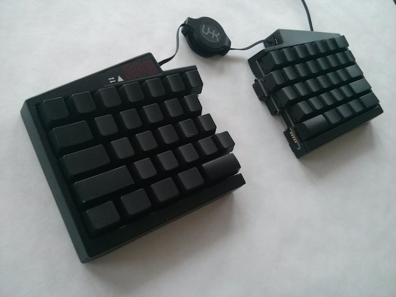
Arduino based Developer's Dream Keyboard


BY LÁSZLÓ MONDA - SOFTWARE ENGINEER @ TOPTAL


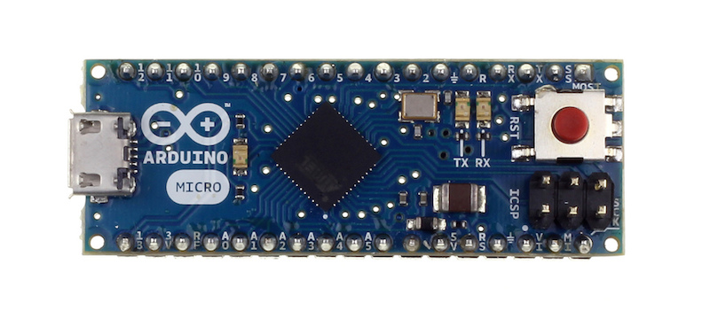
 The Arduino Micro development board is an ideal candidate for this purpose, because it features the ATmega32U4 microcontroller - an AVR microcrontroller and the same processor that is the brains of the UHK.


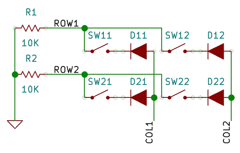
A full-sized 104-key keyboard could have 18 rows and 6 columns but we’ll simply have a humble 2x2 keyboard matrix for starting up. This is the schematic:


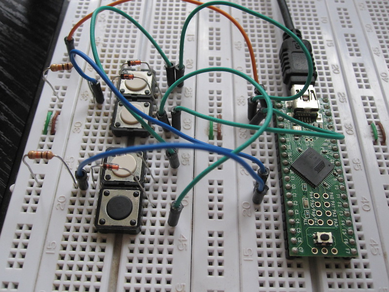
And this is how it looks on a breadboard:


For detailed information about this project follow the link.

Tuesday, May 31, 2016

How I Made a Fully-Functional Arduino Weather Station


BY FRANCISCO SANCHEZ CLARIÁ - SOFTWARE DEVELOPER @ TOPTAL


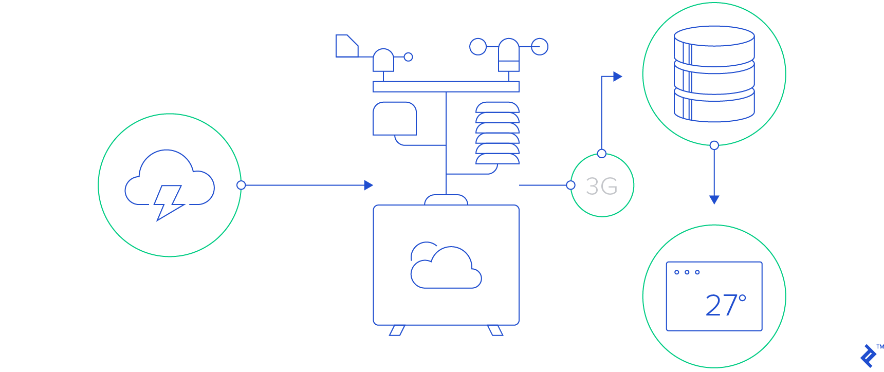
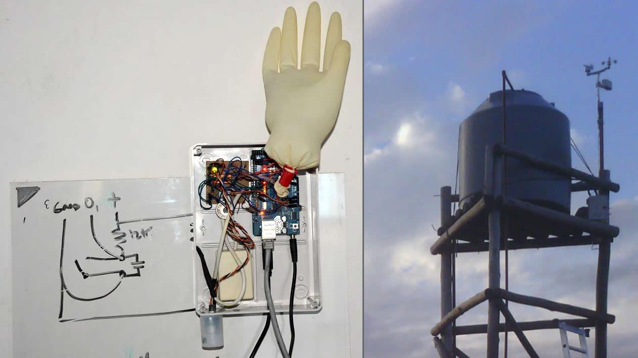
The goal of this project was to deliver real-time weather data to the browser at home.
The key questions and caveats involved in a project like this:

  • How can I create a weather station that it is neither valuable nor attractive to a thief?
  • How can I keep hardware costs and development time to the minimum?
  • How can I measure and access weather data in real time and display it in a useful way?
  • Required measurements: wind and wind gusts, wind direction, rain, atmospheric pressure, temperature, humidity
  • Connect station to Internet
  • Store and retrieve local weather data
  • Communicate between weather station and server
  • How can I reduce maintenance to (almost) zero?
  • Manage hanging of software
  • Manage loss of connectivity
  • Manage loss of energy supply


For detailed information about this project follow the link.
How I Made a Fully-Functional Arduino Weather Station


Friday, May 06, 2016

Arduino Your Home & Environment: Monitoring voltage of a dc battery supply

Arduino Your Home & Environment: Monitoring voltage of a dc battery supply by Steve Spence:


Since we are involved in off grid solar power systems, we have a need to monitor battery voltage. The Arduino can do this easily with a simple voltage divider. With some simple mods, we can control loads, generators, or notifications based on battery voltage.


To read a maximum of 20vdc, R1 should be 3k ohm, R2 should be 1k ohm, and the code would be as follows:


/*

DisplayMoreThan5V sketch

prints the voltage on analog pin to the serial port

Do not connect more than 5 volts directly to an Arduino pin.

*/


const int referenceVolts = 5; // the default reference on a 5-volt board

//const float referenceVolts = 3.3; // use this for a 3.3-volt board


const int R1 = 3000; // value for a maximum voltage of 20 volts

const int R2 = 1000;

// determine by voltage divider resistors, see text

const int resistorFactor = 255 / (R2/(R1 + R2));

const int batteryPin = 0; // +V from battery is connected to analog pin 0


void setup()

{

Serial.begin(9600);

}


void loop()

{

int val = analogRead(batteryPin); // read the value from the sensor

float volts = (val / resistorFactor) * referenceVolts ; // calculate the ratio

Serial.println(volts); // print the value in volts

}

Arduino Basics: Bluetooth Tutorial 1

Arduino Basics: Bluetooth Tutorial 1 by Scott C:  

Introduction: The bluetooth shield used in this project is a great way to detach the Arduino from your computer. What is even better, is that the shield allows you to control your arduino from your mobile phone or other bluetooth enabled device through simple Serial commands. In this tutorial we will connect a Grove Chainable RGB LED to the bluetooth shield directly, and send simple commands using the Bluetooth SPP app on a Samsung Galaxy S2 to change the colour of the LED (Red , Green and Blue)

Notes:
You don't need to download a library to get this project running. But if you plan to use bluetooth shields to get 2 Arduinos to communicate to each other, then I would advise that you download the library files (which are just examples) from the Seeedstudio site : here.

Visit this site to setup your phone or laptop for bluetooth communication to the shield - here

The app used on my Samsung Galaxy S2 phone was "Bluetooth SPP"

You will initially need to enter a pin of '0000' to establish a connection to the Bluetooth shield - which will appear as "SeeedBTSlave" or whatever text you place on line 90 of the Arduino code above.


Warning !

Not all phones are compatible with the bluetooth shield. 
If you have used this shield before - please let me know what phone you used - so that we can build a list and inform others whether their phone is likely to work with this project or not. Obviously - those phones that do not have bluetooth within - will not work :).
And I have not tried any other apps either

I got it to work very easily with my Samsung Galaxy S2 using the free Bluetooth SPP app from the google play store.

Arduino for Beginners: Digital Clock with 7-segments LED and RTC (Realtim...

Arduino for Beginners: Digital Clock with 7-segments LED and RTC (Realtim... by Stanley Seow: Arduino 7-segment RTC After making so many Arduino prototypes on a breadboard, I decide to make something useful that everyone in the house can use. What is more useful that a digital clock as the year 2010 is coming to an end. I starter doing my research on making a digital clock and gathering the components needed to make one. One of the criteria is that all the components must be easily available locally in Kuala Lumpur, Malaysia. Visually, it looks like those countdown timer bomb found on old movies where the hero needs to cut some wires to deactivate the bomb.

In order to make a clock to tell the time, I have a few options, either set the time in Arduino, keep the Arduino power on all the time but this method is not very feasible as I would need to set the time everytime I need to power cycle the Arduino. The second option was an idea of a hugh 7-segments LED powered by a GPS from Sparkfun article. As GPS give a very accurate time, this option should good and I do not need to set the clock everyime it was powered on. I took out my Garmin GPS60C, plug in the serial connection to the Arduino, load a few GPS libraries and I got myself a very accurate time. The problem with this method is that since I live in the middle of Kuala Lumpur, a concrete jungle with condominium surrounding my condominium unit, I need to put an external GPS antenna outside my windows to receive GPS signal directly from the sky. Without a satellite lock, the GPS unit was not able to receive any satellite signals from the key. And the clock either need to be close to the window or I had to run GPS antenna to the place I put my 7-segments digital clock.

The third method is the best, running Arduino with a DS1307 realtime clock (RTC) powered by a 3V coin size battery that can keep the time when it is powered off or during power cycle. I went to the local electronic heaven called Jalan Pasar (market street in english), located in a very congested part of town and try my luck to find the necessary components. To my surprise, I found all the necessary parts to built this digital clock. The main components are :-

- Arduino board
- Four red 7-segments LED ( could not find other cool colour locally )
- DS1307 realtime clock
- 32.768 kHz crystals
- coin size battery holder
- Four shift registers 74HC595 to control the 7-segment LEDS
- resistors and hookups cables
- header pins and integrated circuit/chip (IC) sockets

As I have not acquired the skills to make a printed circuit board (PCB) yet, I decide to use a veroboard ( board with holes to make the components permanent also called a doughnut board ) and solder all the header pins and IC sockets. All the 7-segments LEDs and IC can be easily replaced with this method. As the board size is quite limited, I can only fit four 35mm size 7-segments LED and have enough space for a battery holder. I wanted to get a much bigger 7-segments LED but the bigger ones would requires higher voltage above the 5V and my circuit would need to support dual power rails. I did not want to deal with a dual voltage power regulator circuit at the moment and focus on making my first digital clock.


This Arduino digital clock only uses 5 pins, 3 digital pins for the 74595 shift registers and 2 analog pins for the RTC using I2C connection. What is different between my Arduino Digital Clock vs the commercial digital clock is that I can control the behavior of the clock and can easily add any functions I see fit. Some ideas are like alternating display between hours/minute and minute/seconds,  playing a tune every 1 hour, add in a LM35 to double as a thermometer, sound an alarm in the morning or even control other electrical appliance via a solid-state relay based on time related events or readings from other sensors. As the four digit are quite big and bright, I can use it to display other information too.


I discovered the first issue after I soldered the first digit from the 74595 shift registers to the common cathode 7-segments LEDs. I only use one 220 ohm resistor connected to the common cathode to save the number of resistors needed and found that the number 8, all segments turn on was very dim. This is okay for a prototype but this is not acceptable for a real useful digital clock. Would be very annoying to have different digits with different brightness. So I remove all the wires and went out to get a lot of 220 ohm resistors to connect them to each of the seven segments.


The second issue I found was that I forgot to allocate space for two 5mm LEDs as the colon to blink as a second indicator after I soldered the third digit. As it is quite a lot of work just to make one digit with all the soldering, joining the resistors to the wires, I decide to do away with the 2 colon dots between the hour and the minute digits. I will find a way to install a LED or two as second indicators. The photo in the current photo, I just blink LED on pin 13 for 500 ms delays.

Here are some photos of the finished working product, now I just need to some some acrylic to mount the board and hide the Arduino board behind the digital clock.


Arduino for Beginners: Arduino Pins - Analog style output - Pulse Width M...

Arduino for Beginners: Arduino Pins - Analog style output - Pulse Width M... by Stanley Seow: The last part of the Arduino Pins - Analog Output using Pulse Width Modulation. We have mentioned about digital input, digital output and analog input. How do we do analog output ?

There are no analog output pins on the Arduino and how can I control the intensity or brightness of the LED or variable speed of the DC motor or fan. Yes, you can do analog output style,  it is called Pulse Width Modulation (PWM) and Arduino have a function called analogWrite() to accomplished this with digital pins. This is done by turning on and off the digital pins very quickly at a rate of 500 times per seconds ( frequency of 500Hz).

If you look at the Arduino UNO board, there are ~ beside the following pins - 3, 5, 6, 9, 10 and 11.  These are the PWM pins you can use. To use the analogWrite(), the syntax are :-

analogWrite( pin, dutyCycle );


The pins are 3,5,6,9,10 and 11 and the dutyCycle is a value from 0 to 255..


If you want the LED to be 100% brightness or the PC fan running at full speed, set the dutyCycle to 255. If you want 50%, set the dutyCycle to 128. If you look at the Aduino Fade example, it uses pin 9 instead of the pin 13 for Blink example.  This is because pin 13 is not a PWM pin.

Please note that the function analogWrite() have nothing to do with the Analog Pins!!!

An application of PWM is most commonly found in CPU air cooler with 4 wires to control the speed (RPM) of the fan based on the temperature sensor of the CPU. This is to reduce the noise level by controlling the speed (RPM) of the fan.

Arduino for Beginners: Controlling fan or motor speed with PWM

Arduino for Beginners: Controlling fan or motor speed with PWM by Stanley Seow: On the first part, I talk about switching any 12V DC or higher electronic components ON or OFF. This can be easily done using an optoisolator and a 12V reed relay. In this article, I will be using a different component to control the speed of the 12V fan or motors using Pulse Width Modulation (PWM).

The TIP-122 are Darlington transistors that can support voltage up to 100V. It consist of two transistors with resistors and diode all inside a TO-220 package. You can use TIP-120 that support up to 60V. Please refer to the TIP-120/TIP-122 datasheets for details specifications here.


The input of the circuit is using analogRead(0) to read the light level from the light dependent resistors (LDR). Depending on the light level, the value is converted by the ADC to 0 to 1023. Since the PWM can only take value of 0-254, I will divide the ADC value by 4  to match the PWM value.

The 12V DC supply is separate from the Arduino 5V supply but shared a common ground.


The LCD is to display the LDR value for debugging purpose. Cover the LDR or shine a light to it to see the fan speed change.


Arduino Pin 9 (PWM) connect to the TIP-122 Base (B) pin.

The 12V fan connect to the TIP-122 Collector (C) pin and the Emitter (E) pin connect to the Ground.

Arduino Your Home & Environment: Using a 4x4 Keypad

Arduino Your Home & Environment: Using a 4x4 Keypad  by Steve Spence: I was working on a project for someone who needed a keypad for password entry. I couldn't find my 3x4 keypad, but found a 4x4 keypad in one of my parts boxes. I modified the example sketch that comes with the excellent keypad library to work with this particular keypad. I couldn't find a set of extended headers to directly connect the keypad to the Arduino, so I used a small protoboard.


You do need the library from http://playground.arduino.cc/Code/Keypad

I connected all the pins from the keypad, from left to right, to 9-2 on the Arduino. Key output shows in the Serial Monitor. In Part 2 I'll show how to accept and compare passwords.